Magnetic Effects of Electric current.
Magnetic Effect of Electric Current is the Chapter of Physics that covers the syllabus of class 10 gives the basic idea of magnet effects of electric current , circuit and electric appliances
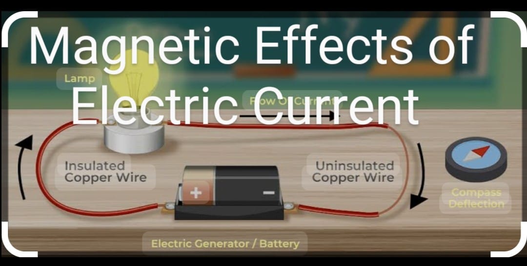
The theory of electromagnetism was given by Hans Christian Oersted in 1820. When he was performing an experiment with the electric current passing through a circuit, he saw that the compass which was present near the circuit began to show major deflections.
This showed that electric current somehow influences the magnetic field around the compass. Hence, the production of magnetic field due to the electric current passing through a conductor is called Electromagnetism.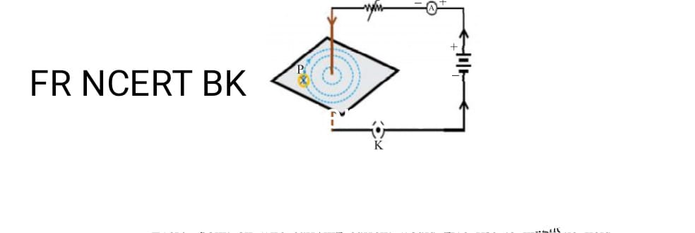
Magnetic Field and Magnetic Field Lines.
By taking an example of a bar magnet, let us understand some features of how a magnet functions. The Bar magnet has two poles: North and South Poles. Like Poles repel each other and Unlike Poles Attract each other. The magnetic field lines are generated from this Magnet. Its features are: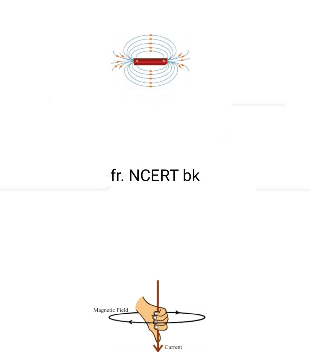
a. The Magnetic field lines originate from the North Pole and Terminate at the South Pole.
b. The extent to where Magnetic pull can be obtained by the magnetic field lines is known as Magnetic field. It is a vector quantity. It has both magnitude and direction.
c. Inside the magnet, the field lines move from south to north pole.
d. The closer the magnetic field lines, the stronger the magnetic field.
e. No two magnetic field lines intersect each other.
Let us take an example of making a circuit with two or three cells, a plug key in the circuit. Keep a compass nearby, if the current flows through the circuit clockwise, then the
compass’ needle will deflect from north to south. If the current is reversed i.e. Anti-clockwise, then the needle will also deflect in the opposite direction. Hence, we can say that Direction of current influences the direction of the magnetic field.
Deflection of the compass needle depends upon two factors:
a. The intensity of the current: The higher the current, the higher the deflection.
b. The distance from the circuit: closer to the circuit, higher the deflection.
Right Hand Thumb Rule:
The direction of the magnetic field can be found out using a simple technique. Where the fingers of the right hand form the direction of the magnetic field’s direction and the thumb form the direction of the current.
For example, if the current is moving from south to north, hence, the direction of the magnetic field as determined by the right-hand thumb rule is in anti-clockwise direction.
This is also known as Maxwell’s corkscrew rule.
When we tighten a nail on a board, if the nail is in downward direction, then magnetic field is in clockwise direction and if it is upward direction, magnetic field is in anticlockwise direction.
Magnetic field due to current through a circular loop:
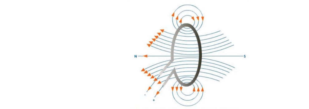
We have seen how the current would flow through a straight current carrying conductor. But if the conductor is bent into a shape of a circular loop, the magnetic field forms slightly different.
We need to understand that the magnetic field is inversely proportional to the distance from the conductor i.e. magnetic field are stronger near the conductor.
Hence, at every point concentric loops will be created which when coincide will result into formation of big circles and as we reach the centre, the loops will form straight line.
The magnetic field produced will be as strong as the number of turns seen in the coil.
Magnetic field through a solenoid: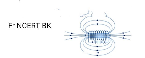
Force exerted on the current carrying conductor in the Magnetic field
It was understood by French Scientist Andre Marie Ampere that in a magnetic field, the magnet exerts an equal and opposite force of the conductor.
Hence, If the magnetic field causes a metal object to move in west direction, if the current is reversed, the direction of the force is also reversed i.e. east.
It can be understood by Fleming’s Left Hand Rule: The rule states that displacement of the conductor is the most when the direction of current and magnetic field are mutually perpendicular to each other.
Hence, The three fingers need to be stretched out from your left hand such that they are mutually perpendicular to each other. i.e.
a. Thumb: The direction of the force on the conductor.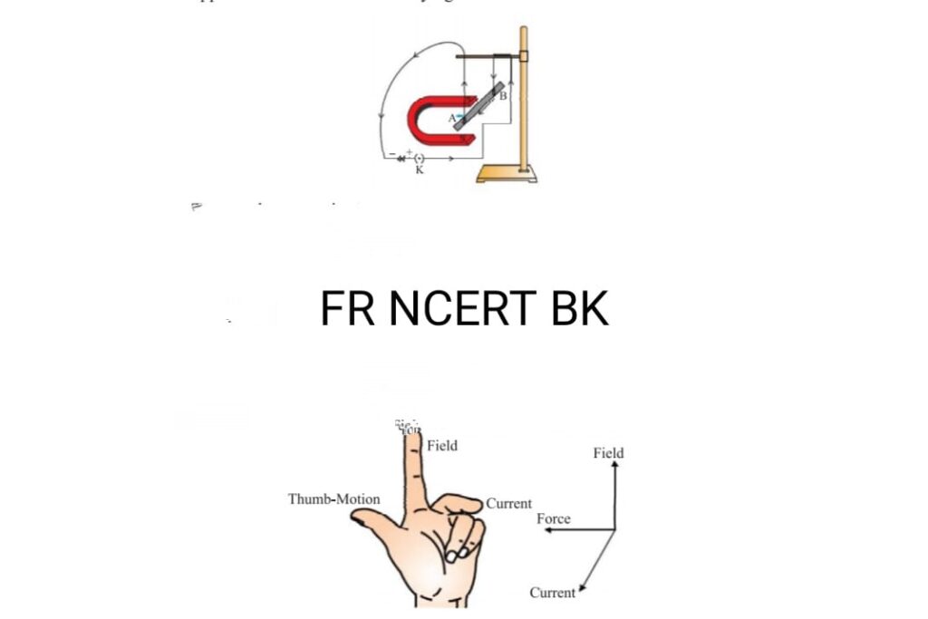
b. Index Finger: The direction of the magnetic field
c. Middle Finger: The direction of the current.
A coil of many circular turns of insulated copper wire wrapped closely in the shape of a cylinder is called a solenoid.
The magnetic field lines produced inside a solenoid is very similar to the bar magnet, since one end of the solenoid acts as a south pole and the other acts as a north pole.
A solid piece of metal can be placed inside the solenoid to be magnetized. Hence, this can be treated as a electromagnet.
ELECTRIC MOTOR: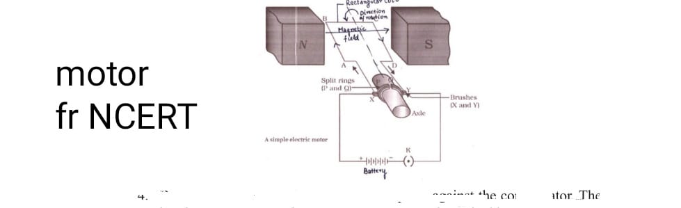
Definition:
An electric motor is a device which converts electrical energy into mechanical energy.
Principle:
The electric motor works on the principle of Fleming’s left hand rule.
Structure:
An electric motor consists of a rectangular loop of copper wire ABCD. The loop is placed between two poles of magnet such that arm AB and arm CD are perpendicular to the direction of the magnetic field.
The ends of the loop are connected to two halves of a split ring P and Q, the inner sides are insulated of the split rings. It also consists of two brushes X and Y.
The split rings are attached to a metal rod called axle which is further connected to a circuit.
Working:
When the circuit is switched on and the current begins to flow through the armature ABCD in such a way that current moves from A to B then B to C and then C to D.
The direction of the current flowing in arm AB is opposite to the direction of the current in arm CD. Now, since the current is in upward direction and magnetic field is produced from North to South pole i.e. in west to east.
By applying Fleming’s left hand rule, we can understand that the force applied on the arm AB is in downward direction, hence, the arm AB begins to move in downward direction and similarly in arm CD, force is applied in the upward direction and CD begins to move upward.
Hence the armature moves in anticlockwise direction. At a half rotation, split ring P comes in contact with brush Y and split ring Q comes in contact with brush X.
Hence, reversing the polarity of the current. Hence, now the current flows through an armature DCBA.
Now, the current is flowing in upward direction in arm DC similar to the arm AB earlier. By applying fleming’s left hand rule, arm DC moves downward to complete a rotation.
A device that reverses the direction of flow of current through a circuit is called a commutator. In electric motors, the split ring acts as a commutator.
Applications: Electric Motor is used in electric fans, mixers, washing machines, computers, etc.
Electromagnetic Induction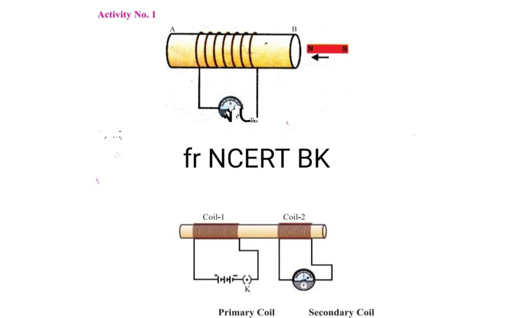
The concept of Electromagnetic induction was given by Michael Faraday, He found that a changing magnetic field in the electric circuit induces an electric current through the circuit.
The property of inducing a current by changing the magnetic field around a circuit is known as Electromagnetic induction.
A galvanometer is a device which is used to detect the presence of the induced current through the circuit. The scale usually points at zero signifying that no current is being induced. But when the magnet is inserted in the circuit, it deflects in a certain direction.
The induced current is the highest when the motion of the conductor is perpendicular to the magnetic field produced in the circuit. Hence, we can understand this by Fleming’s Right Hand Rule.
The fingers of the right hand are as follows:
a. Thumb: The motion of the conductor.
b. Index Finger: The magnetic field. Middle Finger: The induced current.
All three are placed in such a way that they are mutually perpendicular to each other.
ELECTRIC GENERATOR: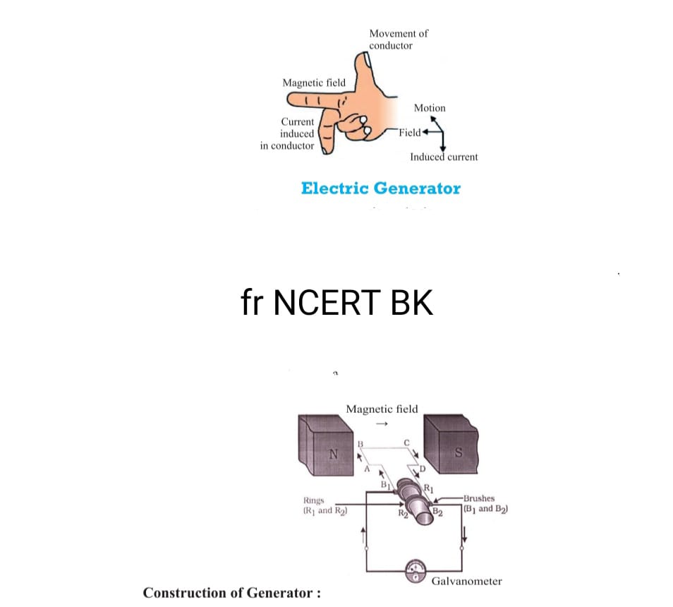
Definition:
A device which uses mechanical energy to rotate a conductor in the magnetic field to produce electrical energy is known as Electric generator.
Principle:
Electric Generator works on the principle of Electromagnetic induction.
Structure:
A rectangular loop of coil ABCD is placed between two poles of the magnet. The two ends of the coil are connected to two rings R1 and R2. Inner side of the ring is insulated. The rings are connected to stationary brushes B1 and B2. The rings are connected to an axle which is further connected to a galvanometer to show the induction of current in the circuit.
Working:
When the axle rotates armature ABCD in clockwise direction such that AB arm moves up and CD arm moves down between the two poles of the magnet. By Fleming’s right hand rule, the current is induced in the direction of ABCD and it flows from B2 to B1.
After half rotation, the armature DCBA moves in such a way that CD arm moves upwards and AB arm moves downward, now the current flows in the direction of DCBA and it flows from B1 to B2.
Thus after every half rotation, the current changes its direction. Hence, such a current which changes its direction after every regular interval is known as Alternating Current. Such a generator which induces alternating current is called AC generator.
To generate a direct current, a split ring commutator is used, one brush is connected at all times with one arm moving up and the other brush is connected to the other arm. Hence, this provides a unidirectional flow of current. This type of generator is called DC generator.
In India, alternating current changes direction after every 1/100 second, hence, the frequency in India is 50 Hz. AC is better than DC because alternating current can be spread across long distance without the loss of energy.
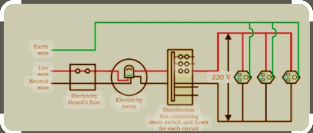
Domestic Electric Circuit
The Electric Power supplied through Main Supply is called Mains.
There are three types of wires that supply the current through our electricity circuits.
a. Red Wire (Live Wire) : Positive
b. Black Wire (Neutral Wire) : Negative.
c. Green Wire (Earth Wire)
Potential difference between two wires is 220 V in India.
The metallic body is connected to the earth wire, which provides a low-resistance conducting path for the current. Thus, it ensures that any leakage of current to the metallic body of the appliance keeps its potential to that of the earth, and the user may not get a severe electric shock.
A fuse in a circuit prevents damage to the appliances and the circuit due to overloading.
Overloading can occur when the live wire and the neutral wire come into direct contact.
In such a situation, the current in the circuit abruptly increases. This is called short-circuiting.
The use of an electric fuse prevents the electric circuit and the appliance from a possible damage by stopping the flow of unduly high electric current.
The Joule heating that takes place in the fuse melts it to break the electric circuit. Overloading can also occur due to an accidental hike in the supply voltage.
Sometimes overloading is caused by connecting too many appliances to a single socket.
Conclusion : Magnetic Effect of Current
The magnetic effect of electric current is a basic principle that has numerous practical applications in our daily lives. This phenomenon demonstrates the intricate relationship between electricity and magnetism. An electric current flowing through a conductor produces a magnetic field around it and The strength of this magnetic field depends on the amount of current and the distance from the conductor.
The direction of the magnetic field can be determined using the Right-Hand Thumb Rule.. This effect is used in electromagnets, which have various applications like in electric bells, loudspeakers, and MRI machines. The interaction between a current-carrying conductor and a magnetic field results in a force, which is the basis for electric motors. As technology advances, the magnetic effect of electric current continues to play a crucial role in developing new and more efficient electrical and electronic devices.
Read More : Electricity
Follow us on : Facebook
Follow us on : Instagram